
Page 94 - Vol.03
P. 94
Special Report 特別企劃 Tech Notes 技術專文 New Visions 新象新知 LOHAS Column 樂活園地
092 093
System design and Kjeldahl method in the laboratory. acid circulation could be adjusted by
measurement setup Later, when the 14-inch system process control. During pilot trials and
was operationa l, the a m mon ia later in the plant, the acid flow was
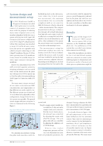
Fig.5. NH3 removal dependence on waste
measurement was occasiona l ly adjusted automatically to one third of
n 2002 Membrana GmbH in water temperature
Wuppertal Germany installed completed with an ion sensitive the waste water flow as this flow ratio
Ia TMCS pilot plant to test the NH4-N-Elektrode (Nadler MiniCal was found to be the most optimum.
removal of ammonia from waste - online measurement). The compact
water with the purpose of reducing measurement technique includes a
waste water disposal costs at the flow-through cell with pH adjustment Results
manufacturing plant. In the first step, a from high-pH caustic water to pH of 5
system utilizing two 6x28 Liqui-Cel® to fully react incoming NH3 into NH4, he goal of the Liqui-Cel®
Contactors (2x1 system configuration) which is measured immediately and Contactor TMCS system
with X-50 Celgard® polypropylene online. After validation of the system Twas to remove 90% of the
hollow fiber membrane was installed the concentrations were measured only ammonia at the Membrana GmbH
to treat 0.5-1 m³/hr of waste water. on the inlet to the municipal water. plant site. The performance of the
Later, the system was expanded with The me a s u r e me n t s e t u p for system has exceeded expectations
a third contactor containing an X-40 ammonium sulphate was done by with a removal rate of 95% [5].
Celgard® membrane. Because X-40 has density control of a first recirculation Some of the dependencies are shown
lower porosity than X-50 membrane tank for the process acid. A second for the 6-inch and 14-inch systems Fig.6. NH3 removal dependence on waste
water flow rate
it was chosen for possible impact on tank was installed for storing the high with two contactors in series in the
water vapor transport through the content ammonia sulphate solution. following figures to demonstrate how
membrane. Depending on the filling level, the fluid the process can be influenced and
After it was determined that X-50 was pumped from the first tank to the where process optimization might be
still provided superior ammonia
stripping performance and successful Fig.4. NH3 removal dependence on waste water pH
trials on the 6inch system the plant
was redesigned in 2004 to operate up
to 30 m³/hr with a 2x1 system utilizing
14x28 Liqui-Cel Contactors with X-50
fi ber.
The waste water stream consisted
of two inlets with different NH3
concentrations and temperatures so
that different test cycles could be run.
The different system sizes (6-inch and temperature was relatively constant at 6 illustrates NH3 removal at different The acid and caustic consumption
14-inch) where fully adjustable so that 45-50°C. waste water flow rates with two 14- depends on the inlet water, the pH, the
configuration changes from 1x2 to a Fig ure 5 shows the ammonia inch contactors in series while one 14- water temperature and the ammonia
2x1 system were possible. The general removal at different temperatures and inch Contactor has a membrane area of content. When the inlet parameters are
system design with two contactors in second tank. flow rates while pH was controlled in 220 m². In this period, the temperature closest to being in the free ammonia
series is illustrated in the following obtained. During evaluation the NH3 the range of 10 to 11.5. The maximum of 50°C and the pH of 10-11.5 were held state, with concentrations suitable for
Figure 3. The pH as major control variable was inlet concentration was approximately process water temperature was limited relatively constant. membrane contactor treatment and
recorded for all inlet and outlet 1300 ppm with minimum to maximum to 50°C because of the limitation of When looking at the ratio of that fit within the operating window
Fig.3. Basic P&ID of a TMCS system with two samples from each contactor. inlet concentration of 600-2500 ppm. the membrane contactor housing membrane area of 6-inch (42 m²) of the TMCS process, less acid and
contactors in serial [4] For the waste water phase, As already shown in figure 1 the materials. Also, as mentioned above, compared to 14-inch (220 m²) no caustic will be required.
the inlet pH was controlled pH and temperature of the waste as temperatures increase, the amount typical water flow per membrane During the trials the generated
by adjusting the caustic soda water influences the free ammonia of water vapor passing through the square meter could be found. This ammonia sulphate concentration was
(NaOH) dosage. The acid content. Since only free ammonia gas membrane also increases. This dilutes made scaling up and down for system up to 30%, which was of very good
phase inlet pH was controlled can be removed by the hydrophobic the acid solution thereby increasing sizing and determining the most quality, but still with pH<4. So before
by adjusting the sulphuric acid membrane, the pH and temperature H2SO4 consumption. economical option difficult. On it could be used as fertiliser it was
(H2SO4) dosage. have a d i rect i n f luence on the D u r i n g pi lot i n g it cou ld b e future systems, connecting additional processed in an evaporation column to
W h i le t h e i n le t obtainable removal rate. In Figure shown that for a 6-inch Contactor contactors in parallel or in series for increase the concentration. The waste
temperature, pressure and flow 4 the ammonia removal is therefore with a membrane area of 42 m², the process optimization is possible but water after the TMCS plant with pH<10
The ammonia measurement during rate were dependant on waste shown as a function of the waste water performance was best at a flow rate more testing is required to obtain was sent directly to the municipal
the pilot trials was done with the water and production parameters, the pH and the flow rate. The waste water between 0.5 m³/hr and 1 m³/hr. Figure actual data. water system.
NEW FAB TECHNOLOGY JOURNAL http://nfjournal/ July 2011