
Page 14 - Vol.17
P. 14
Tech
Notes
技術專文
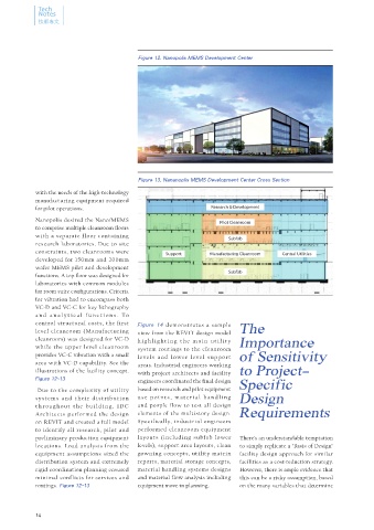
Figure 12. Nanopolis MEMS Development Center
Figure 13. Nananoplis MEMS Development Center Cross Section
with the needs of the high-technology
manufacturing equipment required
for pilot operations. Research & Development
Nanopolis desired the Nano/MEMS Pilot Cleanroom
to comprise multiple cleanroom floors
with a separate floor containing
Subfab
research laboratories. Due to site
constraints, two cleanrooms were Support Manufacturing Cleanroom Central Utilities
developed for 150mm and 200mm
wafer MEMS pilot and development
Subfab
functions. A top floor was designed for
laboratories with common modules
for room suite configurations. Criteria
for vibration had to encompass both
VC-D and VC-C for key lithography
a n d a n a l y t i c a l f u n c t i o n s . To
control structural costs, the first Figure 14 demonstrates a sample
level cleanroom (Manufacturing view from the REVIT design model The
cleanroom) was designed for VC-D h i g h l i g ht i n g t he m a i n ut i l it y Importance
while the upper level cleanroom system routings to the cleanroom
provides VC-C vibration with a small leve ls a nd lower leve l suppor t of Sensitivity
area with VC-D capability. See the areas. Industrial engineers working
illustrations of the facility concept. with project architects and facility to Project-
Figure 12~13 engineers coordinated the final design Specific
Due to the complexity of utility based on research and pilot equipment
systems and their d istr ibution use p oi nt s, m ate r i a l h a nd l i ng Design
t h roug hout t he bu i ld i n g, I D C and people flow to test all design
Architects performed the design elements of the multistory design. Requirements
on REVIT and created a full model Specifically, industrial engineers
to identify all research, pilot and performed cleanroom equipment
preliminary production equipment layouts (including subfab lower There's an understandable temptation
locations. Load analysis from the levels), support area layouts, clean to simply replicate a "Basis of Design"
equipment assumptions sized the gowning concepts, utility matrix facility design approach for similar
distribution system and extremely reports, material storage concepts, facilities as a cost-reduction strategy.
rigid coordination planning ensured material handling systems designs However, there is ample evidence that
minimal conflicts for services and and material flow analysis including this can be a risky assumption, based
routings. Figure 12~13 equipment move-in planning. on the many variables that determine
14