Page 53 - Vol.06
P. 53

Building       Column Spacing    Beam Size        Girder Size            Slab
               A  Steel/RC        21’4” × 32’0”@85.3” c/c  W27 × 84  W30 × 116    3.5” nwt concrete on 2” metal decking
                  (fully fitted out)
               B  Steel/RC        21’0” × 28’1”  W21 × 44/W21 × 73 @84” c/c  W24 × 76/W24 × 84  3.25” lwt concrete on 3” metal decking
                  (core & shell)
               C  RC
                  (fully fitted out)  21’0” × 27’0”  12”W × 14”D @42” c/c  30”W × 24”D  5” nwt concrete
               D  Steel/RC        28’6” × 28’6”  W16 × 31 @9.5’ oc  21”W × 73”D   3.25” lwt concrete on 2” metal deck
                  (ductwork & partitions)
              Table 6. Floor geometry and Construction


                  are calculated.                              30000

                2.  Calculate                                  25000
                                                                                                       SCI P076
                                                               20000
                3.  The peak velocity vn in each mode n                                                AISC
                  at point i on the floor due to walking      rms velocity, min/s  15000               BBN
                  at point j is calculated                     10000                                   Arup

                  using               where                                                            Measured
                  are the mode                                 5000
                  shape deflections at point i and j;            0
                                                                       A       B        C       D
                  and    is the mode mass                                         Floor
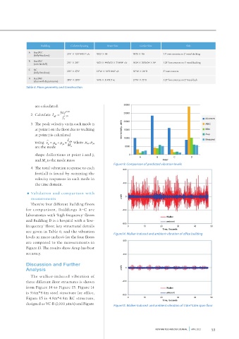
                                                          Figure13. Comparison of predicted vibration levels
                4.  The total vibration response to each
                                                              800
                  footfall is found by summing the
                  velocity responses in each mode in
                  the time domain.                            400
              •  Validation and comparison with
                measurements                                  m/s  0
                There’re four different Building floors
              for comparison, Buildings A–C are               -400
              laboratories with ‘high-frequency’ floors
                                                                                    Walker
              and Building D is a hospital with a ‘low-                             ambient
                                                              -800
              frequency’ floor; key structural details           0       10      20      30       40      50
                                                                                  Time, Seconds
              are given in Table 6; and the vibration     Figure14. Walker-induced and ambient vibration of office building
              levels in micro-inches/s for the four floors
                                                              800
              are compared to the measurements in
              Figure 13. The results show Arup has best
              accuracy.                                       400

              Discussion and Further
              Analysis                                        m/s  0
                The walker-induced vibration of
              three different floor structures is shown       -400
              from Figure 14 to Figure 15. Figure 14                                Walker
              is 9.6m*9.6m steel structure for office,                              ambient
                                                              -800
              Figure 15 is 4.8m*4.8m RC structure,               0       10      20      30       40      50
                                                                                  Time, Seconds
              designed as VC-B (1,000  in/s) and Figure   Figure15. Walker-induced  and ambient vibration of 4.8m*4.8m span floor


                                                                              NEW FAB TECHNOLOGY JOURNAL         APRIL 2012  53
   48   49   50   51   52   53   54   55   56   57   58