
Page 54 - Vol.06
P. 54
Tech
Notes
技術專文
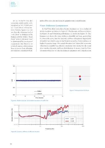
1 6 i s 4 . 8 m *4 . 8 m R C induced but also take mechanical equipment into consideration.
structure with waffle slab,
+
designed as VC-D (180 in/ Floor Stiffness Comparison
s). From these vibration-
time history figures we can A 9.6m*9.6m floor with three beams, hammer test was conducted
see that the vibration level of at two locations as shown in Figure 17. The dynamic stiffness is shown
in Figure 18 and vibration performance is shown in Figure 19. The
“soft floor” is dominated by
hammer test shows the static stiffness of middle and near quarter bay
human activity, while a “hard
floor” which vibration level is almost the same, but the dynamic stiffness (frequency dependent)
is dominated by mechanical of middle bay which is just at the beam location has better stiffness at
equipment. But there’re no higher frequency range. The actual vibration level shows the maximum
related papers elaborating vibration is at middle bay which is consistent with theory, but the trend
how to assess floor vibration, also matches dynamic stiffness distribution. It means that the floor
not only just consider footfall- vibration when has to take mechanical equipment into consideration
800
400
m/s 0
-400
Figure17. Measurement locations
Walker
ambient
-800
0 10 20 30 40 50
Time, Seconds
Figure16. Walker-induced and ambient vibration of waffle slab
1.E+10
Dynamic Stiffness, N/m 1.E+09 quater
1.E+08
1.E+07 middle
1 10 100 1000
Frequency (Hz)
Figure18. Dynamic stiffness of different location
54