Page 20 - Vol.06
P. 20

Special
             Report
             特別企劃


                  Plant B                      7.1
             111.9
                               30.0           30.0
              W                            6
                               5.7            22.9
                        R            33.0     33.3
                        C            0.3   7        R
                       W             2.4
                               0.3            53.3
                                              55.0                                  28.3
                                           8
                            54.7                               25.0              6.7             35.0
                                               5.6                 9                           11
                                                                         25.0
                                                         196.8                R     23.2
                                                               70.0                              40.0
                                                           W       10    75.6  C    16.8       12
                                                                              W
                                                                                    5.3
                  Plant A      3.5                             45.0  15  20.9                  13  8.0
                                                                         24.1     2.7
                  50.0
                       1
                                       16.4
                                                                                  49.9           49.9
                         33.6              2  34.0                                             14
             113.1            R  30.5
                   8.0   8.0                                   Plant C                                 R
              W        4      C
                              W
                  51.6   3.2          7.9     7.9
                                           5        R
                          0.1
                       3
                          54.8
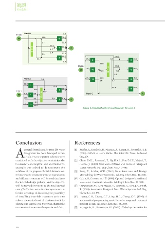
                                                             Figure 4. Resultant network configuration for case 2


            Conclusion                                 References

            A                                          [1]  Brooke, A., Kendrick, D., Meeraus, A., Raman, R., Rosenthal, R.E.
                   general formulation for inter-fab water
                                                          (2003). GAMS: A User's Guide. The Scientific Press. Redwood
                   integration has been developed in this
                                                          City, CA.
                   article. Five integration schemes were
            considered with the objective to minimize the   [2]  Chew, I.M.L., Raymond, T., Ng, D.K.S., Foo, D.C.Y., Majozi, T.,
            freshwater consumption, and an illustrative   Gouws, J. (2008). Synthesis of Direct and Indirect Interplant
            example was solved to demonstrate the         Water Network. Ind. Eng. Chem. Res., 47, 9485.
            validness of the proposed MINLP formulation.   [3]  Feng, X., Seider, W.D. (2001). New Structure and Design
            In future work, treatment units for regeneration   Methodology for Water Networks. Ind. Eng. Chem. Res., 40, 6140.
            and effluent treatment will be combined into   [4]  Galan, B., Grossmann, I.E. (1998). Optimal design of distributed
            the inter-fab design problem, and the objective   wastewater treatment networks. Ind. Eng. Chem. Res., 37, 4036.
            will be turned to minimize the total annual   [5]  Gunaratnam, M., Alva-Argáez, A., Kokossis, A., Kim, J.K., Smith,
            cost (TAC) for cost-effective operation. A    R. (2005). Automated Design of Total Water Systems. Ind. Eng.
            further advantage of discussing the possibility   Chem. Res., 44, 588.
            of installing inter-fab treatment unit is to   [6]  Huang, C.H., Chang, C.T., Ling, H.C., Chang, C.C. (1999). A
            reduce the capital cost of treatment unit by   mathematical programming model for water usage and treatment
            sharing it in central area. Moreover, sharing the   network design. Ind. Eng. Chem. Res., 38, 2666.
            treatment units can save the space in each fab.   [7]  Karuppiah, R., Grossmann I.E. (2006). Global optimization for


            20
   15   16   17   18   19   20   21   22   23   24   25