
Page 71 - Vol.43
P. 71
4.5 Silica Recycling Plant(SRP) coupling agent are added to increase powder dispersion and
improve lipophilicity during surface modification process. The
4.5.1 Plant Scope
addition of the dispersant is to increase the specific surface
SRP will process about 9,600 tons/yr of CMP sludge and area of AlSiO x powder to makes it difficult for the particles to
generate about 5,700 tons/yr of industrial grade of AlSiO x form agglomerates and promotes the uniform dispersion of
product used for plastic filler. The major compositions of CMP the particles in the matrix resin. Add coupling agent : Silica-
sludge are shown in Table 5 and the product specification is in aluminum oxide is an inorganic powder with hydrophilic
Table 6. surface. The addition of the coupling agent such as silane
coupling agent lets the surface of the powder becomes
Table 5、The major compositions of CMP Sludge lipophilic from hydrophilic surface, or improve the compatibility
Item Compositions with the lipophilic matrix resin so as to increase the thickness of
Water content 50% the interface and improve the toughening effect. After surface
SiO 2 (dry basis) 60%
Al 2 O 3 (dry basis) 10% modification, the AlSiO x powder is bagged and transferred to
storage bunker.
See the process flow diagram in Figure 19 below.
Table 6、The product specification of AlSiO x
Item Main Product 4.5.3 Plant Layout
Copper content ≦ 23mg/kg
Water content ≦ 1% As shown in Figure 20 below, the CMP sludge will be
Silica content ≧ 95%
Particle size ≦ 10㎛ shipped by trucks from F15A or F15B, and transferred it to
CMP sludge storage area. Then CMP sludge is transferred to
4.5.2 Process Introduction Process area for extraction of copper, drying, crushing, surface
modifying, and bagging.
CMP sludge is sent to Reactor Tank for the separation
and extraction of heavy metals. H 2 SO 4 is added to selectively 4.5.4 Project Milestone
extract copper from sludge. After extraction and enrichment, As shown in Figure 21, the supplier will take about 4
the sludge is separated into solid phase and liquid phase by months to apply CTSP member in order to rent the land and
gravity sedimentation in Settling Tank and the alkaline solution apply construction permits. The construction will start around
is added to precipitate copper hydroxide to separate and 10/E in 2021 and take about 9 months to complete including
extract copper from the AlSiO x sludge. Then the AlSiO x sludge equipment installation. The operation permits may take about
is through the rotary dryer at about 500℃ to remove>99% 11 months. Thus the commissioning will start around July 2023
of the water. Then the AlSiO x cake is crushed by Fluidized and the normal operation will start October 2023.
Bed Jet Mill and sieved through to make more uniform
particle size. Then surface modifiers such as dispersant and
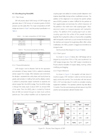
Figure 19、Process Flow Diagram of SRP
FACILITY JOURNAL 09 2021 69