
Page 68 - Vol.43
P. 68
Tech
Notes
技術專文
Figure 12、Project Milestones of ARP Scope
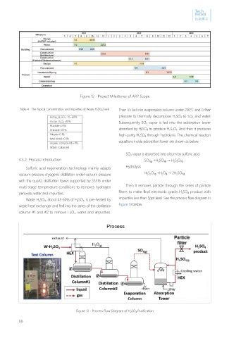
Table 4、The Typical Concentration and Impurities of Waste H 2 SO 4 Feed. Then it's fed into evaporation column under 220℃ and 0.4bar
Assay_H 2 SO 4 : 45~60% pressure to thermally decompose H 2 SO 4 to SO 3 and water.
Assay_H 2 O 2 <10% Subsequently SO 3 vapor is fed into the adsorption tower
Fluoride<0.1%
Chloride<0.1% absorbed by H 2 SO 4 to produce H 2 S 2 O 7 . And then it produces
Nitrate<0.1% high-purity H 2 SO 4 through hydrolysis. The chemical reaction
total metal<0.1% equations inside adsorption tower are shown as below.
organic compounds<1%
Water : balanced
SO 3 vapor is absorbed into oleum by sulfuric acid.
4.3.2 Process Introduction SO 3(g) +H 2 SO 4(l) → H 2 S 2 O 7(l)
Sulfuric acid regeneration technology mainly adapts Hydrolysis
vacuum pressure cryogenic distillation under vacuum pressure H 2 S 2 O 7(l) +H 2 O (l) → 2H 2 SO 4(l)
with the quartz distillation tower supported by SS316 under
multi-stage temperature conditions to removes hydrogen Then it removes particle through the series of particle
peroxide, water and impurities. filters to make final electronic grade H 2 SO 4 product with
Waste H 2 SO 4 , about 45-60% of H 2 SO 4 , is pre-heated by impurities less than 5ppt level. See the process flow diagram in
waste heat exchanger and fed into the series of the distillation Figure 13 below.
column #1 and #2 to remove H 2 O 2 , water and impurities.
Figure 13、Process Flow Diagram of H 2 SO 4 Purification
66