
Page 73 - Vol.43
P. 73
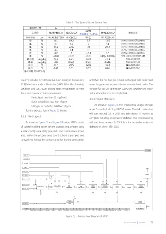
Table 7、The Types of Waste Solvent Feed


                system) includes SNCR(Selective Non-Catalytic Reduction),   and then the hot flue gas is heat-exchanged with boiler feed
                SCR(Selective catalytic Reduction)/GGH(Gas Gas Heater),   water to generate required steam in waste heat boiler. The
                Scrubber and WESP(Wet Electro-Static Precipitator) to meet   exhaust flue gas will go through SCR/GGH, Scrubber and WESP
                the environmental emission requirement.            to the atmosphere via 27 m high stack.
                        Particulates : less than 25 mg/Nm3
                                                                   4.6.4 Project Milestone
                        Sulfur oxide(SOx) : less than 45ppm
                                                                       As shown in Figure 25, the engineering design will take
                        Nitrogen oxide(NOx) : less than 90ppm
                                                                   about 5 months including HAZOP review. The civil construction
                    See the process flow in Figure 22 below.
                                                                   will start around 9/E in 2021 and take about 15 months to
                4.6.3  Plant Layout
                                                                   complete including equipment installation. The commissioning
                    As shown in Figure 23 and Figure 24 below, STRP consists   will start from January 15 2023 thus the normal operation is
                of control building, spent solvent storage area, process area,   debuted on March 16 in 2023.
                auxiliary facility area, utility pipe rack, and maintenance access
                area. Within the process area, spent solvent is pumped and
                sprayed into furnace by sprayer Lance for thermal combustion


                                                  Figure 22、 Process Flow Diagram of STRP


                                                                                             FACILITY JOURNAL        09  2021  71