
Page 75 - Vol.15
P. 75
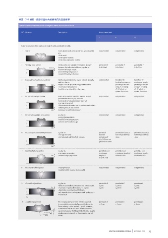
表五、DVS 規範 - 管路焊道缺失檢驗項目與品質標準

              External condition of the surfaces of single-V welds and double-V welds

                NO. Feature               Description                  Acceptance level
                                                                       I           II           III


                External condition of the surfaces of single-V welds and double-V welds
                1  Cracks                 Cracks aligned with weld or oriented across to weld,   not permitted  not permitted  not permitted
                                          e.g.:
                                          -in the weld.
                                          -in the parent material.
                                          -in the zone exposed to heating.
                2  Welding bead notches   Clearly visible and palpable depressions along or   permissible if  permissible if  permissible if
                                    K > 0  between the individual weld runs, e.g. due to:  0<k≤0.3×d  0<k≤0.4×d  0<k≤0.5×d
                                          -fault in the hot gas nozzle.
                                          -poor welding rod guidance.
                    S
                                          -incorrect bead layer structure.
                3  Edge notches/continuous undercut  Notches (undercuts) in the parent material along the   not permitted  Permitted for   Permitted for
                                          weld, e.g. due to:                       localized occurrences   continuous lengths
                                      S   -edges of nozzle tip penetrating parent material.  providing the notch   providing the notch
                                          -incorrect joint preparation.            sides are not steep   sides are not steep
                    S                     -insufficient welding of the edge zones.  ∆S≤0.1s but not   ∆S≤0.1s but not
                                                                                   greater than 1mm  greater than 1mm
                4  Incomplete root penetration  Notch in the root because filler material has not   not permitted  not permitted  not permitted
                                          penetrated to the root, e.g. because:
                                          -bevel angle of prepared edge is too small.
                                          -root gap is too small.
                    S                      Filler material rod or wire used for root run was too thick.
                                          -welding pressure was too low.
                                      S   -joint was not preheated enough.
                5  Incompletely welded cross-section  e.g. due to:     not permitted  not permitted  not permitted
                                          -poor edge preparation.
                                          -insufficient welding pressure.
                                          -joint not preheated enough.
                    S
                                      S
                6  Excessive penetration/root protrusion  e.g. due to:  permitted   permissble if ∆S≤0.2s   permissble if ∆S≤0.2s
                                          -root gap too wide.          localized   but not greater than   but not greater than
                                          -root run made with too high pressure.  occurrence if   3mm  4mm
                                                                       ∆S≤0.15s but not
                    S                                                  greater than 2mm
                                      S
                7  Bead too high/excess filler  e.g. due to:           permitted over   permitted over   permitted over
                                          -too many runs applied.      continuous   continuous lengths if   continuous lengths
                                      S   -incorrect edge preparation.  lengths if   0.05s≤∆S≤0.5s  if 0.05s≤∆S≤0.6s
                                                                       0.1s≤∆S≤0.4s
                    S


                8  Incompletely filled groove  -missing final run.     not permitted  not permitted  not permitted
                                          -insufficient filler material fed into weld.


                9  Mismatch of joint faces  e.g. due to:               permissble if  permissble if  permissble if
                                          -differences in wall thickness were not compensated.  e 1 ≤0.1s  e 1 ≤0.15s  e 1 ≤0.2s
                                     e 2  -materials of equal wall thickness not aligned.  e 2 ≤0.1s  e 2 ≤0.15s  e 2 ≤0.2s
                                          -depending on material and thickness:
                    S                     such imperfections can impair the weld quality, e.g. in
                                          PP and PVDF.
                    e 1
                10  Angular misalignment  If it is not possible to conform with the required,   permissble if  permissble if  permissble if
                                          i.e. permissible angular misalignment limits due to   e≤3mm  e≤5mm  e≤8mm
                                          factors relating to the materials, crystallinity, joining
                                          of different materials and sheet thicknesses, then
                                       e  experimental proof shall be provided that the angular
                                          misalignment is due only to the properties named
                                 300      above.


                                                                              NEW FAB ENGINEERING JOURNAL         SEPTEMBER 2014  73