摘要

There has been much discussion lately as to the relevance of multi-pass welds on UHP gas supply systems. Much of the confusion as to the acceptance of multi-pass welds on small bore piping, ½” and smaller in diameter stems from the practice being used in Taiwan for the past 20 years. Even though this may have been the standard for the industry in the late 1980’s through the early 1990’s, much has changed due to studies on corrosion processes in the HAZ (Heat Affected Zone) and on the welds themselves.
Multi-pass welding
In the late 1980's through the early 1990's it was determined that narrow internal weld beads were desirable when joining 316L stainless steel pipe/tube and fittings for semiconduc-tor manufacturing facilities. This determination was due to assumption that as the weld area did not meet the surface roughness standards of ≤ 10µinch Ra, a narrow weld bead would disturb a smaller area of the internal surface of the tube/pipe. As the sur-face roughness was considered to effect the generation of particles, the less disturbed surface area would be more acceptable.
Dr. T. Ohmi of Tokyo University made extensive studies into orbitalelding of stainless steel delivery sys-tems for UHP gas delivery systems in the early to mid 1990's. During these studies Dr. Ohmi noted that multi-pass welding using a pulsed welding system produced a weld with a very narrow internal bead width. This lead to multi-pass welds being incorporated into the welding procedures in many places around the world.
But Dr. Ohmi soon realized that multi-pass welding imparted much more heat into the weld area. This affected the Heat Affected Zone (HAZ), the area just adjacent to and on both sides of the weld, sensitizing the material in the HAZ, making these areas more susceptible to corrosion when exposed to certain gases and compounds. This lead Dr. Ohmi to revise his initial recommendations and revert to recommending single pass welds for all thin walled stainless steel tube/pipe distribution systems.
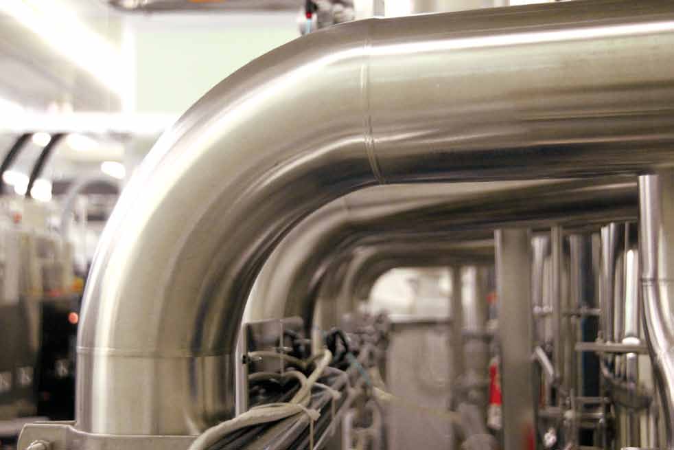
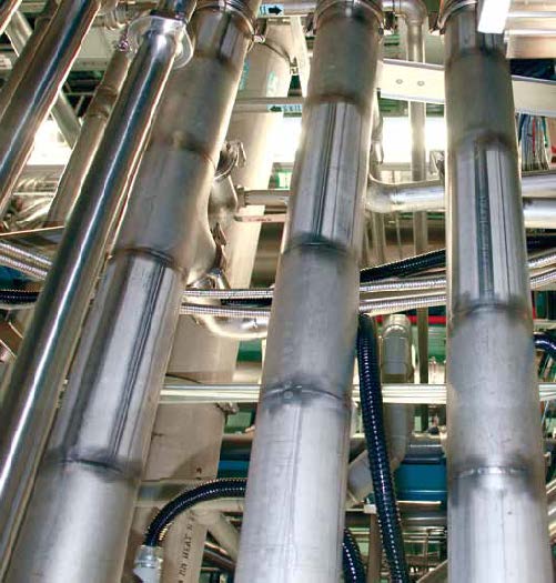
External view of a single pass weld on 150A BA 316L S/S Pipe.
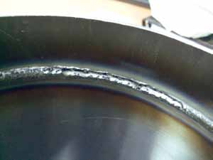
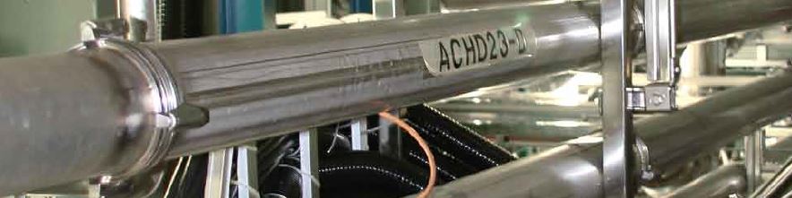
External view of two pass weld on 150A BA 316L S/S Pipe. Note portion of initial weld that was not consumed but second pass.

Weld Mechanics
As a result of the welding process Fe (iron), the major constituent of 316L and 304L stainless steel, is re-deposited on the surface of the weld joint and in the HAZ. This is caused by a number of processes such as convection and electro/magnetic currents inside the weld puddle and vaporization of the parent material during the welding process. This redistribution of Fe causes the areas of re-distribution to be more susceptible to corrosion when exposed to certainsubstances . This redistribution of iron can be demon-strated by holding a small magnet to the surface of the parent material well beyond the weld areaand the HAZ and noting that the magnet is not attracted to the parent material. When the same small magnet is held near the weld itself the magnet will be attracted to the weld surface.
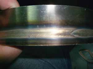
Internal view of two pass weld on 150A BA 316L S/S Pipe. Note portion of weld where “suck back” has occurred due to reheating of the weld area during second pass.
Even single pass welds have an area that is welded more than once; there is a small area where the end of the weld overlaps the start of the weld. This overlap of the weld is done to assure that the weld has been com-pleted around the entire joint. It has been noted during corrosion experi-ments conducted on 316L stainless steel piping, that these areas of over-lap of the weld show more corrosion than do the other portions of the weld area. This would indicate that the weld area that has been re-melted during the overlap is more susceptible to corrosion than the portions of the weld that are only melted one time.
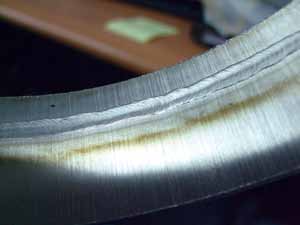
Internal view of single a pass weld on 150A BA 316L S/S Pipe.
Conclusion
The number of times that 316L or 304L stainless steel material is melted and allowed to re-solidify at ambient temperature has a direct affect on the corrosion resistance of the material. If it were possible to clean and repassiv-ate the areas after welding, the corro-sion resistance of the joint would be improved. This repassivation is common in the bio-pharmaceutical industry, but is not practical in the semiconductor industry. As the proce-dure for repassivation requires the chemicals for passivation, usually a strong acid to remove free Fe ions from the surface of the material, to be distributed via an aqueous solution this is not practical for use in UHP gas service systems.
Of course, if a gas system will not be exposed to corrosive gases it may be allowable to make multiple pass welds without regard to the reduced corrosion affect. This would need to be carefully monitored closely to assure that corrosive gas piping was welded using a single pass process. This would be very time consuming and not very cost effective as multiple pass welds are most commonly only employed when joining piping used in gas systems that are ½” and smaller, usually special gas piping.
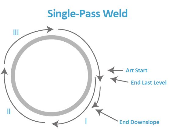
Orbital tube welding is done as a fusion GTA weld on a square end preparation, usually in a single pass. Weld current is reduced around the weld circumference in a series of steps or levels. A timed current downslope completes the weld.
There are also instances where double pass welding must be employed. When hand welding, it is more effective to employ a joint that has beveled edges and a gap between the two members.
These members are then joined by filling the gap between them with a filler metal of the same or similar chemical composition to the parent material. In most cases these types of joints are more effectively joined by welding them twice. The first pass joining the two members and the second pass filling the space left due to beveling the pipe. As this type of welding is most commonly done on large systems, >150mm in diameter, and larger systems are normally used to deliver inert gases such as Argon, Nitrogen, or CDA (Clean Dry Air) they are not exposed to corrosive sub-stances.
Finally, it has been determined that it is more cost effective to pro-duce weld beads that are 2T, T being the wall thickness of the parent mate-rial, in width than it is to make 1T welds with no loss of corrosion resis-tance. An experiment was done where 1T and 2T welds were tested under the same conditions and there was no indication that the 2T welds were any more susceptible to corrosion than the 1T welds, but when welds were pro-duced over 2T in width there was a substantial increase in corrosion. Also, it was determined that it takes up to 3X longer to develop a program for 1T welds than for 2T welds due to the precision required to weld consistent 1T welds.
In almost all cases throughout the U.S., companies have moved away from multi-pass welds for UHP gas delivery systems, opting instead for a weld that is 2T in width and single pass. In fact, in the revision to the SEMI Standard SEMI F78-0304, PRACTICE FOR GAS TUNGSTEN ARC (GTA) WELDING OF FLUID DISTRIBUTION SYSTEMS IN SEMI-CONDUCTOR MANUFACTURING APPLICATIONS in 2007 the param-eters for an acceptable weld ID bead were changed from 1~1.5T to 1~2.5T, thus allowing ID bead widths up to 2.5T. With all of this in mind it would be suggested that much consideration go into the decision to use multiple pass welds to join piping systems ≤ 150mm in diameter. The susceptibility of these multiple pass welds to corro-sion is very apparent, not to mention the added value of the single pass 2T welds on small diameter tube systems, ≤1/2” in diameter.
參考文獻
- S.H. Lin, "Corrosion protection of high copper aluminum alloys and stainless steels by surface modification," Ph.D. thesis University of Southern California, 1995.
- Barbara K. Henon, “Tube Welding -Orbital Welding of 316L Stainless Steel Tubing,” Arc Machines, Inc., Originally presented at the Twelfth Annual World Tube Congress, October 7-10, 1996, spon-sored by the Tube and Pipe Association, International (TPA)
留言(0)